Get an instant quote
Get in touch Listen to our podcast

Blog

How to Choose the Right Electrical Substation?

Choosing the right Electrical Substation is a practical decision with long-term consequences. It affects power quality, public safety, maintenance costs, and network resilience. A unit that looks adequate on paper may struggle under heat, dust, flooding, or sudden load growth. Real conditions matter.

Load forecasts, fault levels, voltage class, available land, and future expansion shape the selection. Engineers also examine soil resistivity, salt pollution, fire separation, and access for heavy transformers. These details are easy to overlook. A coastal site may need stronger corrosion protection than an inland location. An urban project may require gas-insulated equipment because space is limited. That choice can reduce the footprint, but it often increases capital and maintenance costs. No single design fits every network.

This guide combines practical project considerations, manufacturer information, and established IEC or IEEE guidance. Local grid codes and utility requirements must still control the final design. Readers will examine transformer capacity, busbar arrangements, protection systems, grounding, automation, and environmental conditions. Reliability also depends on testing, spare parts, operator training, and safe maintenance access. A cheaper transformer may become expensive when losses, outages, and repairs are included. Small assumptions can distort the result. Even experienced teams may underestimate future demand or site hazards. That uncertainty deserves attention, not confident wording. The best choice balances proven performance, regulatory compliance, lifecycle value, and realistic operating conditions.
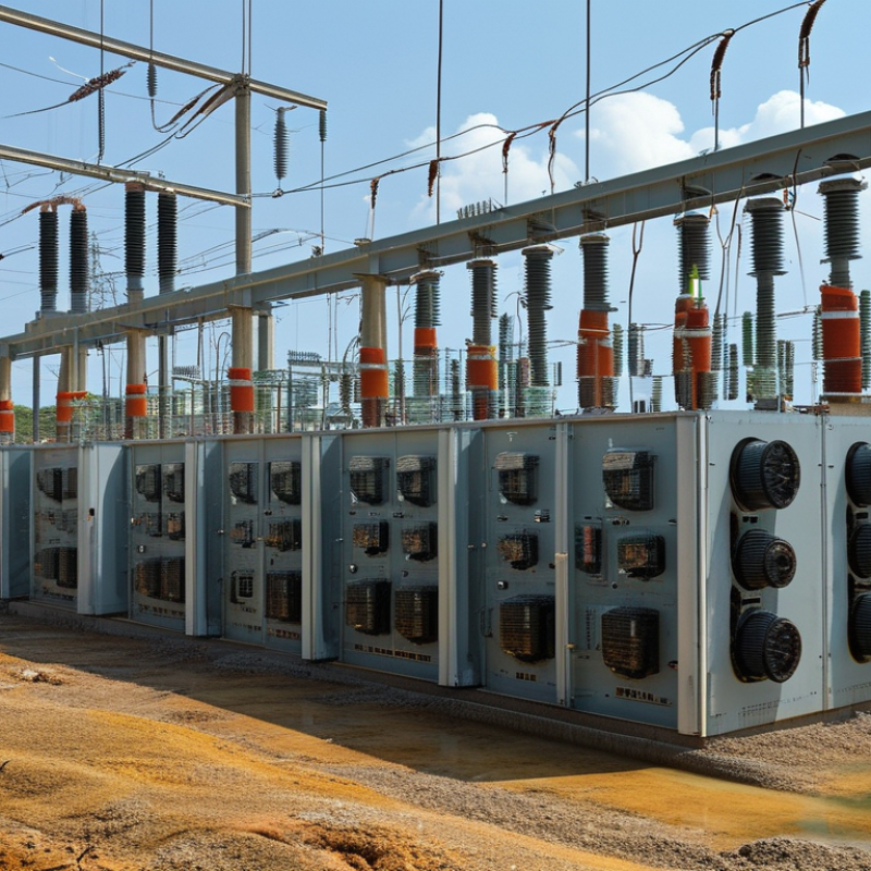
How to Choose the Right Electrical Substation?

Define Load Demand, Voltage Class, and 20-Year Capacity Growth

How to Choose the Right Electrical Substation?

Define Load Demand, Voltage Class, and 20-Year Capacity Growth

Choosing a substation starts with the actual load, not the transformer nameplate. List present equipment, operating hours, starting currents, and seasonal peaks. Separate essential loads from flexible or intermittent loads. A motor starting at 6:00 a.m. can create a sharper demand than its running rating suggests. Demand changes.

Use measured data when possible. Temporary power-quality meters can reveal harmonic distortion, voltage dips, and hidden peak loads. If measurements are unavailable, document every assumption and apply a realistic demand factor. I have seen projects fail because estimated diversity was too optimistic. That mistake is expensive to correct later.

Voltage class must match the utility connection, insulation requirements, fault levels, and site distribution plan. Higher voltage may reduce current and cable losses, but it can increase clearance, protection, and maintenance demands. A qualified electrical engineer should verify short-circuit ratings and coordination under applicable codes.

Then model capacity for twenty years. Include production expansion, electric vehicle charging, new buildings, and efficiency changes. Compare normal demand, emergency demand, and future peak demand separately. Reserve physical space for another transformer or feeder where practical. A staged expansion plan may cost less than installing excess capacity today.

A forecast is never perfect. Review it annually, especially after major equipment changes. Allowance for uncertainty is not wasted capacity; it is disciplined risk control.

Size Transformers for Peak kVA, 80–90% Loading, and N-1 Reliability

Choosing the right electrical substation begins with the transformer load profile, not the average monthly demand. Record peak kVA during production changes, motor starts, welding cycles, and extreme weather. A transformer operating near 80–90% of its rated capacity usually balances efficiency and practical growth. Continuous operation at 100% leaves little room for cooling limits or unexpected demand. Ambient temperature matters. So does harmonic current from electronic equipment.

N-1 Reliability N-1 reliability means the system can continue operating after one transformer or major component fails. This requires more than installing two identical units. Review feeder capacity, transfer arrangements, protection settings, and the largest single load. For example, two transformers may share normal demand, but one unit must carry essential loads during an outage. That calculation can expose a weak design. A tidy spreadsheet can still be wrong if field measurements are incomplete.

Tips: Use measured 15-minute demand data when possible. Add realistic future growth, not optimistic guesses. Check transformer impedance and short-circuit levels with the protection engineer. Leave space for maintenance access and heat dissipation. Test the proposed N-1 condition before approval. Recheck the design after major equipment changes. Small errors become expensive.

Select 1–52 kV Switchgear Under IEC 62271-200 Requirements

Choosing an electrical substation begins with the switchgear’s operating range. For medium-voltage systems, 1–52 kV equipment should match the network’s voltage, load current, and short-circuit level. IEC 62271-200 is central here. It covers AC metal-enclosed switchgear above 1 kV and up to 52 kV.

Check the tested ratings, not only the catalogue values. A 12 kV panel, for example, may need a specific short-time withstand current for several seconds. Review the rated peak withstand current, insulation level, and internal arc classification. IAC ratings should reflect the operator’s position, such as AFL or AFLR. The installation room matters. A rating tested with doors closed may not represent every maintenance condition.

Service continuity also deserves close attention. IEC 62271-200 uses LSC categories to describe how safely compartments can remain energized during access. Partition class, such as PM or PI, affects separation between live parts and cable compartments. Ask for type-test documentation and verify its exact configuration. Small differences matter.

Think beyond the substation drawing. Dust, condensation, altitude, cable bending space, and repeated switching can change performance. I have seen projects prioritize a compact footprint, then struggle with cable termination access. That choice was efficient on paper. It was not efficient in the field. Protection settings, earthing arrangements, interlocks, and maintenance procedures must fit the actual network. Do not treat compliance as a checkbox. Recheck the assumptions before ordering.

How to Choose the Right Electrical Substation?

IEC 62271-200 applies to AC metal-enclosed switchgear and controlgear above 1 kV and up to and including 52 kV. The chart shows commonly standardized rated-voltage classes used when defining medium-voltage switchgear.

Selection should match the system’s nominal voltage and include suitable insulation, short-circuit withstand, internal-arc, service-continuity and environmental ratings. Final equipment specifications must be verified against the applicable IEC requirements and the installation conditions.

Calculate Fault Current and Coordinate Protection Within IEEE Standards

How to Choose the Right Electrical Substation?

Calculate Fault Current and Coordinate Protection Within IEEE Standards

Choosing a substation begins with a defensible fault-current study. Collect utility fault levels, transformer impedance, cable lengths, conductor sizes, and motor contributions. Record the X/R ratio, not only the available kilovolt-amperes. It affects the asymmetrical peak and breaker duty. For a three-phase fault, estimate current with Isc ≈ V / (√3 × Ztotal). Then verify the result using a detailed impedance model. Fault current is not just one number.

Protection coordination requires a time-current curve for every major device. Plot relay pickup, breaker clearing time, cable damage limits, and transformer withstand values. Set the upstream device slower than the downstream device, where safety and selectivity allow. Check phase and ground faults separately. Include CT saturation, relay tolerances, and breaker operating delays. These small details matter.

Use applicable IEEE guidance, including IEEE 551 for short-circuit studies and IEEE 1584 for arc-flash evaluation. Confirm the adopted editions and local electrical requirements before issuing settings. A field engineer should compare the model with nameplates, tap positions, and actual conductor routes. One overlooked parallel cable can distort the entire study. The first calculation is rarely perfect. I have seen clean spreadsheets fail when old drawings remained unchanged. Treat assumptions as temporary, label them clearly, and retest protection during commissioning. Reliable substation selection depends on measured data, transparent calculations, and settings that technicians can verify safely.

How to Choose the Right Electrical Substation? - Calculate Fault Current and Coordinate Protection Within IEEE Standards

Preliminary comparison of typical substation configurations, fault-current calculations, interrupting-duty requirements, and protection-coordination parameters.

Substation Application System Voltage Transformer Rating Transformer Impedance Available Source Short-Circuit Power Calculated 3-Phase Fault Current Recommended Minimum Breaker Interrupting Rating Typical CT Ratio 51 Pickup Setting Coordination Target Applicable IEEE Guidance
Fault-current and equipment-duty assessment
Medium-voltage industrial service 13.8 kV 10 MVA 7.5% 500 MVA 4.40 kA symmetrical 8 kA symmetrical minimum 600:5 1.20 × transformer full-load current ≥ 0.30 s grading margin to downstream feeder IEEE 141, IEEE 242, IEEE 3002.3, IEEE C37.010
Utility distribution substation 34.5 kV 20 MVA 8.0% 750 MVA 3.14 kA symmetrical 5 kA symmetrical minimum 400:5 1.25 × transformer full-load current ≥ 0.30 s grading margin to feeder protection IEEE 242, IEEE 3002.3, IEEE C37.010
Low-voltage facility substation 480 V 2.5 MVA 5.75% 500 MVA at primary source 48.1 kA symmetrical 65 kA symmetrical minimum 4000:5 1.15 × transformer full-load current Selective coordination with main and feeder breakers IEEE 141, IEEE 242, IEEE 3002.3
Renewable-energy collector substation 34.5 kV 30 MVA 10.0% 600 MVA 3.45 kA symmetrical 8 kA symmetrical minimum 600:5 1.30 × maximum continuous collector current Verify inverter fault-current contribution separately IEEE 242, IEEE 3002.3, IEEE C37.010
Calculation method and protection-coordination checkpoints
Transformer full-load current Three-phase system IFL = S / (√3 × V) Use the transformer MVA rating and line-to-line voltage Establishes the normal-load reference for pickup settings
Transformer short-circuit contribution Per-unit method SSC,tr = Str / Zpu For a 10 MVA, 7.5% transformer: 133.3 MVA Use nameplate impedance at the selected transformer tap
Combined source and transformer fault level Equivalent short-circuit power 1/SSC,total = 1/SSC,source + 1/SSC,tr For 500 MVA source and 133.3 MVA transformer: 105.3 MVA Include utility, motor, generator, and inverter contributions where applicable
Three-phase bolted fault current Symmetrical RMS current ISC = SSC,total / (√3 × V) Compare calculated current with breaker interrupting and bus bracing ratings Evaluate maximum and minimum fault cases for protection sensitivity
Breaker interrupting-duty check Symmetrical current rating Breaker rating ≥ calculated interrupting current Apply an engineering margin and verify X/R asymmetry Check IEEE C37.010 application guidance and the equipment rating documentation
Overcurrent relay pickup 51 time-overcurrent element Typically above maximum load and below minimum fault current Common preliminary range: 1.15–1.30 × maximum continuous current Confirm transformer inrush, cold-load pickup, motor starting, and emergency loading
Instantaneous or high-set element 50 function Set below close-in faults but above downstream through-faults where coordination is required Use only after reviewing the complete time-current curve Avoid nuisance tripping during transformer energization and external faults
Relay coordination interval Primary versus backup protection Time difference at the same fault current Typical preliminary target: 0.20–0.30 s for numerical relays Include relay operating time, breaker clearing time, CT error, and safety margin
Minimum-fault sensitivity Remote-end or line-to-ground fault Verify relay pickup is below the minimum expected fault current Use separate single-line-to-ground and phase-to-phase studies Do not rely only on the maximum three-phase fault calculation
Selection decision criteria
Transformer selection Capacity and impedance Select MVA capacity from diversified demand plus planned growth Review how impedance affects fault current and voltage regulation Consider cooling class, tap range, inrush, harmonic loading, and short-circuit withstand
Bus and switchgear selection Voltage, continuous current, fault duty Continuous rating ≥ maximum load current Interrupting rating ≥ maximum calculated fault current Verify momentary, closing, latching, arc-flash, and seismic requirements as applicable
Protection philosophy Primary and backup layers Use feeder, transformer, bus, and source protection zones Maintain selectivity without sacrificing fault-clearing speed Validate settings with time-current curves and minimum/maximum operating cases
Engineering note: The values shown are realistic illustrative design data for preliminary comparison only. Final equipment ratings and relay settings require a site-specific short-circuit, load-flow, motor-starting, arc-flash, grounding, and protection-coordination study. Fault-current calculations should consider utility operating conditions, transformer taps, conductor impedance, motor and generator contributions, inverter controls, X/R ratio, and both three-phase and unbalanced faults.

Verify Grounding, Safety, Efficiency, Cost, and Lifecycle Compliance

How to Choose the Right Electrical Substation?

A reliable substation begins with verified grounding, not attractive equipment ratings. Measure soil resistivity across the site before selecting the grounding grid. Calculate touch and step voltages under maximum fault conditions. IEEE Std 80 provides established methods for this assessment. A low bid can still be unsafe. Field inspections often reveal buried connections, corrosion, or inaccessible test points.

Safety requires more than physical clearances. Apply IEC 61936-1 to high-voltage installation design, then confirm local protection requirements. Specify arc-resistant construction where the risk assessment justifies it. Include interlocks, remote operation, fire separation, and clearly marked isolation points. Maintenance access matters. A design that works on paper may fail during a rushed outage.

Efficiency and cost should be judged across the entire lifecycle. Compare no-load losses, load losses, cooling energy, harmonic effects, spare parts, and inspection labor. The International Energy Agency’s 2023 Electricity Grids report estimates annual grid investment must exceed 600 billion dollars by 2030. The U.S. Department of Energy estimates its 2024 distribution-transformer rule could save 3.6 quadrillion British thermal units over 30 years. That national figure is not a promise for one site. Recheck assumptions using actual load profiles and climate data. Real projects change.

CNC machining CAD export file formats

Put your parts in production today

Get an instant quote